CNC Conversion - Electronics Enclosure Gets Powered On

Finishing up the Electronics Enclosure for my Grizzly G0704 CNC conversion.
This DIY CNC conversion has been a fun and educational experience so far.
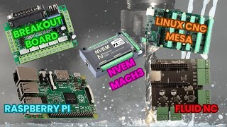
Using a Mesa 7I76E controller card and LinuxCNC the conversion is nearly complete.
Important Note... Don't power on a servo motor system without the motors connected. Mine uses stepper motors and it's OK for my build.
Another Note/Update: At 10:57 in the video I talk about a set of terminal blocks for the Alarm outputs and the need for pullup resistors. I recently discovered the the alarm outputs may be configurable ON SOME DRIVERS, in the driver's configuration software to change the polarity of the alarm output from negative to positive. It's not mentioned in the driver's documentation, but it seems to be an option in the software. If so, the pullup resistors (and those terminal blocks) would not be necessary. On my stepper drivers the alarm output is an optoisolator with a NPN phototransistor output. Since the Mesa card GPIO has input resistance of about 20K Ohms to field power
ground, the emitter can be connected directly to the GPIO pin. I'll be removing the pullup resistors and the related terminal blocks. Not sure how I missed that during the build.
Fan/Cooling Update: With summer arriving, temperatures in the garage are climbing. With greater that 90°F ambient temperature, the stepper drives are hot to the touch. Maybe ~120°125°F. Just to be safe I upgraded the fans to 80mm x 80mm x 25mm (from the 15mm version) and replaced the foam filter with a wire mesh one. The foam dust filter seemed to block about half of the air flow. Now the incoming to outgoing air temperature differential is about 5°F, and the drives feel much cooler.
In the video I talk about running the steppers on lower than rated voltage. I was experimenting with the effect of different (lower) voltages on the steppers. Stepper motors should be run at their rated voltage. If you want to reduce their power and lower their operating temperature because the motors are oversized for example, do it by reducing the current setting on the stepper motor driver. Not by lowering the voltage.
The DCDC Step Down (Buck) Converter Power Module to power the volt/amp meters is designed around the LM2596HVS IC/chip. The module I'm using is rated for up to 53VDC input. The grounds of all the stepper power supplies and all the Volt/Amp meters are tied together. The positive lines are kept separate. One Power supply, the 48VDC ZAxis, power, all three Volt/Amp meters.
The Screw Starter is an Ullman Devices DE1, though they make other models.
The white connectors are Molex brand, for1420 AWG wire. Model Latch Lock, MLX, 2.13mm D.
Part numbers vary depending on the number of pins. I mistakenly said Amphenol connectors in the video. Habit from my aircraft maintenance days.
Chapters:
0:00 Intro
0:14 Epson Label Printer and Software
1:00 Labeling the 24VDC Terminal Blocks
1:38 Exterior Overview
2:09 A Look Inside / Volt and Amp Meters
3:24 Backplane Design Goal / Removing Power Supplies
4:58 Stepper Driver Power Connector Key
5:48 Removing the Backplane
6:59 Installing a few Wire Duct Covers
8:10 System Overview
14:53 Reinstall the Backplane / Screw Starter
17:08 Power On
20:10 Power Off