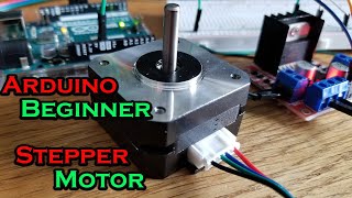
Control Stepper Motor with Arduino - Tutorial

today i will guide you how to control a stepper motor with an arduino and a4988 stepper driver,
we will see how to control its rotation speed with a potentiometer, and change its direction of rotation with a push button.
components we will need;
a stepper motor,
an a4988 stepper motor driver,
an arduino board,
a 100k potentiometer
push button
100mf capacitor
breadboard and connecting wires.
i have also written a code to run the motor on various speeds using a potentiometer to adjust the motor speed.
you will find all the diagrams and arduino files here:
https://goo.gl/15Ebo5
NOTE: arduino code is in folders above schematics :)
buy stepper motors for cheap here:
Stepper Motor NEMA 17: https://goo.gl/1zBdXx
buy links for parts:
(Global):
Arduino UNO micro USB version: https://goo.gl/RNZS5Z
Stepper Motor NEMA 17: https://goo.gl/L17oRL
A4988 Driver: https://goo.gl/bcL5kZ
Potentiometer 100Kohm: https://goo.gl/adwtoJ
India:
Arduino UNO: https://bit.ly/31I0FQf
Stepper Motor NEMA 17: https://bit.ly/3mUykOU
A4988 Driver: https://bit.ly/4br5Lj4
Potentiometer 100Kohm: https://bit.ly/3SXwNrr
the A4988 stepper driver module has total 16 pins
the vmot and ground pins are for the external power for the motor,
you cannot power the motor from the arduino as it requires a minimum of 835 volts
i use a 12 volts 2 amp external power supply. make sure you use a decoupling capacitor to avoid any unnecessary noise.
the next 4 pins are of the stepper motor.
you have to connect the pins with the right polarity, otherwise your motor wont work and make loud noises.
you can determine the polarity of the motor using your multimeter
Each pair of same phase should have no resistance when measured with a multimeter, so you have to check the pairs which have zero resistance
and connect positive and negative of phase A to 1a and 1b, and accordingly for phase b
it is better to check the polarity in the manufacturer information for your motor to avoid this hassle.
you can also connect multiple stepper motors for similar actions in parallel until you do not exceed the current limit
next you have to connect the reset and sleep pin to activate the driver.
the a4988 uses 3.55 volts power so you can power it from the arduino 5v output
connect the digital4 pin of the ardiuno to the direction pin and d3 pin to step pin of the driver.
the ms1,2,3 pins are for enabling microstepping.
you can connect 5 volt input to the pins to enable microstepping. there are 5 different modes for microstepping as shown in the table.
it is also important to limit the current to the motor.
you can do so by setting the potentiometer on the driver to around 30 degrees clockwise for 0.5 amps
first we will run a simple code to run a full rotation and pause for 1 second.
upload the code and you see the motor running.
if not,make sure you have connected all pins correctly. and followed all the procedures
i have also written a code to run the motor on various speeds using a potentiometer to adjust the motor speed.
you have to connect the potentiometer wiper pin to a0 pin of the arduino, and connect 5v input in the first, and ground the third pin
i have another code in which you can toggle the direction of the motor using a push button.
hope you enjoyed the video, please do like share and subscribe, and thanks for watching!
Solder Iron i Use: http://bit.ly/2GSArih
Helping Hand Magnifier: http://bit.ly/2Uh11oe
check out my other projects:
DIY Lab Bench power Supply: • How to make Simple Lab Bench Power Su...
DIY Dremel Tool: • DIY 3D Printed Dremel Tool
Arduino 3D Printer : • How to Make 3d Printer at Home | Ardu...
DIY on off Timer: • DIY Arduino Programmable On/Off Timer...
DIY Quadcopter: • How To Make Drone At Home (Quadcopter...
#steppermotor #steppermotorcontrol #steppermotortutorial #howtocontrolsteppermotor