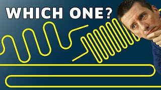
How to design perfect switching power supply | Buck regulator explained

How does a switching power supply work? Signals and components explained, buck regulator differences, how do they work, which one to use, ... By Carmen Parisi. Thank you very much Carmen
Links:
Carmen's LinkedIn: / carpar
Carmen's presentation: https://welldoneblogfedevel.files.wor...
FEDEVEL online courses: https://courses.fedevel.com/
Chapters:
00:00 Main parts of a buck regulator
00:12 Switching power supply controller
02:11 Gate driver and FETs
07:50 Inductor and Capacitor
11:04 Integrated SMPS: Controller + Gate Driver + FETs
14:26 Power supply module
16:07 PMBUS
20:46 Control modes
22:46 DrMOS: Gate Driver + FETs
28:58 Control scheme, Voltage mode vs. Current mode
33:32 What frequency to use in switching power supply?
38:40 About inductor
43:56 About capacitors, capacitor derating
57:55 Gate resistors, ( RGATE )
1:03:29 CBOOT, Boot resistor, ( RBOOT )
1:07:37 How to measure switching power supply signals, probing
1:16:41 Phase snubber ( RSNUB, CSNUB)
1:19:08 VIN Capacitor
1:22:56 Phase node, switching node, ringing
1:28:37 ShootThrough
1:33:36 Dead Time, diodes
1:37:27 Stability / Jitter
1:43:53 Transient response
1:48:49 Multiphase regulators
Would you like to support me? It's simple:
Sign up for online courses hosted on our platform: https://marketplace.fedevel.education/
Sign up for my Hardware design and PCB Layout online courses: https://academy.fedevel.com/
You can also support me through Patreon: / robertferanec
Or sign up for my Udemy course: https://www.udemy.com/learntodesign...
It is much appreciated. Thank you,
Robert