Introduction to orthographic projection

Introduction to Orthographic projection
In this video we will discuss what is meant by Orthographic projection, Principles of Orthographic projection and key points to draw Orthographic projection.
In Engineering drawing commonly four methods of projection are used.
Orthographic projection
Oblique projection
Isometric projection
Perspective projection
First let’s look into orthographic projection for now.
Orthographic projection means the representation of threedimensional objects into two dimensional views on the drawing sheet.
We get these two dimensional shapes using parallel projection technique.
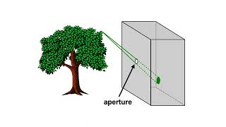
In parallel projection, we project rays or line of sight onto the object that produces two dimensional shapes on the screen or projection plan placed behind the object.
Parallel projection literally means, line of sight or projection lines are parallel to each other.
These projection lines are projected perpendicular to the plane.
So, if the projection lines are parallel to each other and also perpendicular to the projection plane, it is called orthographic projection.
By this projection, the true dimensions of the object will be preserved.
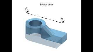
Every 3 dimensional object contains six sides, front side, top side, left side, right side, bottom and rear side.
So, 6 views are possible for a 3 dimensional object.
From these 6 views, 2 views are mandatory to represent a complete dimension of the given 3D object Like length, width, height.
Sometimes it may require 3 views if it is a complex shape. Three views are important among those views.
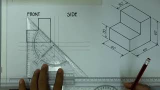
We can represent any object using just 3 views. The 3 views are
Front view
Top view
Side view
We take these views because we cannot represent a 3 dimensional object on paper. So, we convert it into 2 dimensional shapes and draw them on paper.
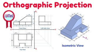
Generally, we follow a format to represent the 3 views on a 2D drawing sheet.
We draw a reference line XY on the drawing sheet.
The front view of the object is drawn above the reference line.
The top view is drawn below the reference line.
And the side view is drawn beside the front view. If we consider the left side view of the object, we draw it right side to front view. If we consider the right side view, we draw it left to the front view.
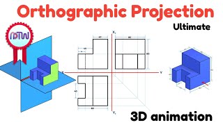
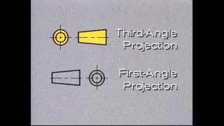
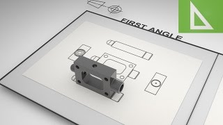
This kind of representation is called 1st angle projection. We will discuss it in the upcoming episodes.
So In this video, we have learned about orthographic projection.
To get more inspiring 2D, 3D video courses and infographics related to this course and all engineering courses, please download Edoreal app.
You will get a great engineering learning community along with all video and infographic courses, to network, to get all your doubts cleared, and to share knowledge.
Mobile: https://play.google.com/store/apps/de...
Website: https://www.edoreal.com/
https://play.google.com/store/apps/de...