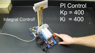
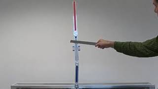
Reaction Wheel Inverted Pendulum -- Arduino PID Control System
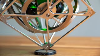
I designed this reaction wheel inverted pendulum in Solidworks and 3D printed the components.
Reaction wheels can apply torques to a system by accelerating or decelerating and are commonly used on satellites to control their orientation. One challenge of reaction wheels is saturation. Saturation of a reaction wheel occurs when the wheel reaches its maximum angular velocity. At this point the wheel can no longer accelerate, and loses the ability to control the system. There are many techniques available to avoid saturation, but the method I chose is target setpoint adjustment based on a state observer.
The motor used is a DC motor from an inkjet printer.
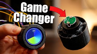
I soldered the custom slip ring together from scrap copper tubing, copper sheet, and the brushes from an old DC motor. The slip ring allows infinite rotation of the pendulum arm while delivering power to the motor.
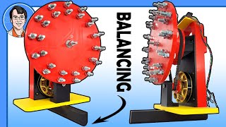
The counterweight washers have the effect of decreasing the controller effort required to control the system. Since the simple DC motor I used does not have a very high power density, this proved necessary.
I used a 5:1 belt reduction to allow the motor to operate closer to its optimal RPM range. This allows for a greater available controller effort. Since frictional losses from a timing belt are roughly proportional to the belt width, I sliced a 6mm GT2 belt in half to create a 3mm wide GT2 belt.
Music by: https://www.bensound.com/freemusicf...
License code: TL01Q0LP0VQB0API