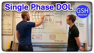
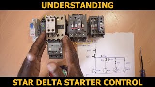
How Star Delta Starters Work - Control Circuit Explained
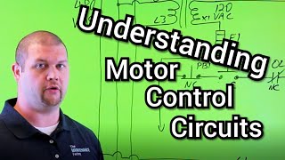
In this video, we delve deep into the workings of star delta starters and their control circuit. Understanding the star delta connection is crucial for anyone involved in motor control systems. We will explore the star delta starter control circuit diagram, breaking down its components and functionality for better comprehension.
Learn how to efficiently wire a star delta starter and recognize common issues associated with star delta connections. We'll provide a clear star delta starter diagram to guide you through the process, ensuring you can implement the wiring correctly.
This video is perfect for electricians, engineers, and enthusiasts wanting to enhance their knowledge of star delta motor connections. We will also cover the use of timers in star delta connections and the importance of contactor wiring.
Join us as we simplify the star delta control wiring and address potential problems you might encounter. By the end of this video, you will have a solid understanding of how to work with star delta starters and their applications in motor control. Don't miss out on this essential guide!
ost induction motors are controlled by the direct online starter, however, the heavy motor with a heavy load if started using a direct online starter Huge voltage surge(voltage surge can damage electronic equipment, small machines and the contractor that is supplying the same circuit)because of the high current that is drawn from the supply.
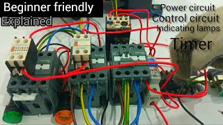
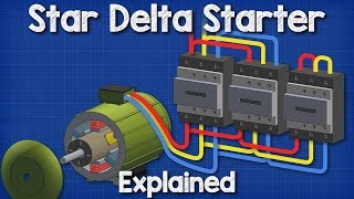
Parts that make up the starter
1) 3 Contactors (main contactor, star contactor and delta contactor)
2) Auxiliary contact(with NC) for each contactor
3) On delay timer
4) Thermo overload relay
5) Control breaker(doublepole)
6) Pushbutton(2)(start and stop)
Here is how the control works or click here https://electrecasolutions.com/unders...
When the ON push button starts the circuit by energizing the star contactor(S) and the timer(T) at the same time. The star contactor(S) gets energized through NC of the timer(T) through NC of the delta contactor(D) When the star contactor(S) is engaged(energized) it closes its auxiliary contact NO through which the main contactor(M) get energized.
The circuit will run for the set period normally (a few seconds) and timer (T) will open NC and close NO through which delta contactor (D) gets energized.
NOT because the main contactor(M) is energized through the star contactor(S), we don't want it(the main contactor) to go off when the star contactor is disconnected, that's why we make a parallel connection between star contact (Y AUX) and main contactor (M AUX2).
STAR DELTA STARTER VIDEO • star delta starter connection 3 phase...
TIMER VIDEO • Delay Timers Explained Which One Sh...
FORWARD REVERSE WIRING DIAGRAM VIDEO • forward reverse switch wiring
FORWARD REVERSE WIRING VIDEO • forward reverse motor control wiring|...
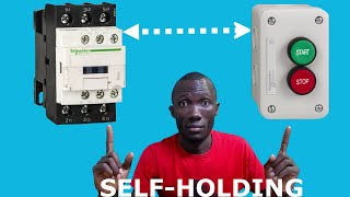
CONTACTOR SELFHOLDING VIDEO • The SelfHolding Push Button Explained
contact me here
[email protected]
follow me on Twitter / davidssengendo
like my Facebook page / electerca
Visit my blog https://electrecasolutions.com/blog/
Buy contactors here https://amzn.to/39iW0p2
Push buttons https://amzn.to/3qN2DpN
AI Digital Multimeter https://amzn.to/2R1Q2mp
Disclaimer: ELECTRECA is a participant in the Amazon Associates Program, an affiliate advertising program designed to provide a means for sites to earn advertising fees by advertising and linking to www.amazon.com